
Designing PCB Mounting Holes Correctly: Things Every PCB Designer Should Know
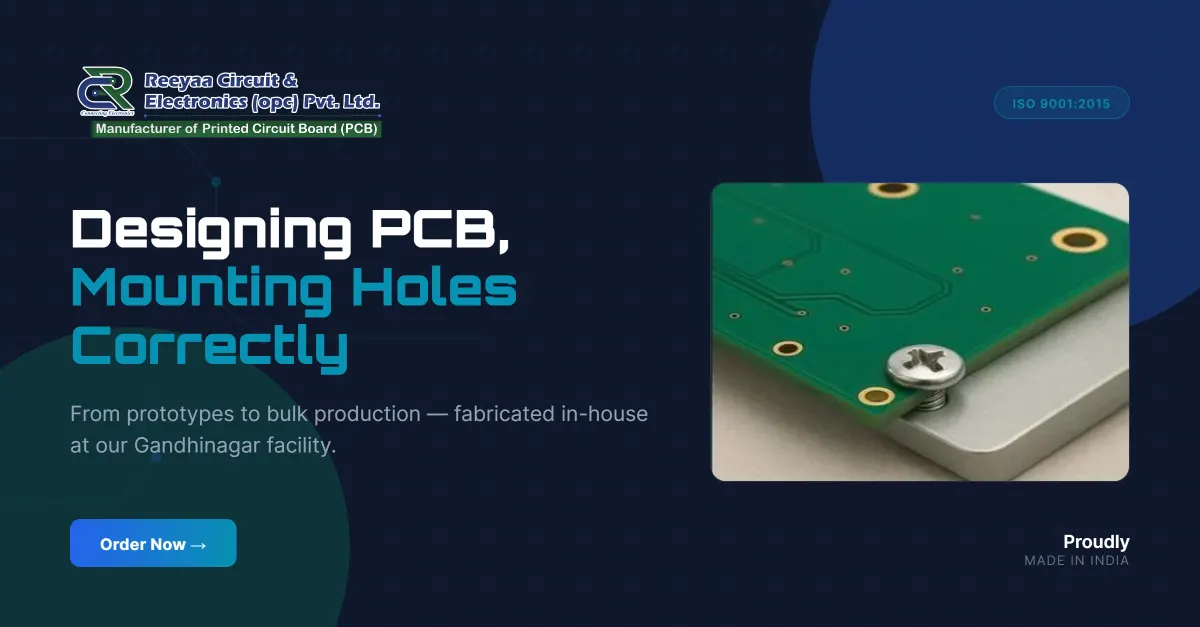
A PCB is not just about electrical connections and components. It also needs to fit properly inside its enclosure or mounting structure.
One important detail that is sometimes overlooked during PCB design is the placement and design of mounting holes. Incorrect mounting hole dimensions or positioning can create problems during assembly, cause mechanical stress, or even damage the PCB.
Whether you are designing a small prototype or a PCB for a commercial product, proper mounting hole design is essential.
1. Choose the Right Mounting Hole Type
Before placing mounting holes, understand the two commonly used types:
Non-Plated Through Hole (NPTH): These holes do not have copper plating on their inner walls. They are commonly used for mechanical mounting with screws, spacers, and standoffs.
Plated Through Hole (PTH): These holes have copper plating on the inner walls and can provide electrical connections between PCB layers. They may also be used for mounting when an electrical connection is required.
For ordinary mechanical mounting, NPTH is generally preferred unless the design specifically requires an electrical connection.
2. Select the Correct Hole Diameter
The mounting hole diameter should match the screw, bolt, or standoff being used.
For example, an M3 screw typically has a nominal diameter of 3 mm, but the PCB hole should provide suitable clearance for easy assembly.
The final hole size depends on the screw dimensions, manufacturing tolerances, and assembly requirements.
Always check the mechanical specifications before finalising the hole diameter.
3. Maintain Proper Clearance Around Mounting Holes
One of the most important considerations is the clearance between the mounting hole and nearby copper tracks, pads, and components.
If copper is placed too close to a mounting hole, the screw, washer, or metal standoff may accidentally make contact with it.
This can cause short circuits or damage during assembly.
Keep a copper-free area around mechanical mounting holes wherever required. Also consider the washer diameter and the size of the mounting hardware, not just the hole itself.
4. Consider Edge Clearance
Mounting holes should not be placed too close to the PCB edges.
Insufficient edge clearance can weaken the board material and increase the risk of cracking, especially when screws are tightened.
Maintain sufficient material around each hole based on the board thickness, hole diameter, mounting hardware, and mechanical loading.
For boards exposed to vibration or mechanical stress, additional consideration may be necessary.
5. Plan Mounting Hole Positions Early
Mounting holes should ideally be considered during the initial PCB layout rather than added at the end.
Check the following:
-
Enclosure dimensions and internal space.
-
Screw and standoff positions.
-
Component height and mechanical interference.
-
Distance from PCB edges.
-
Accessibility for screwdriver and assembly tools.
-
Alignment with other mechanical parts.
For products with fixed enclosures, it is always better to verify the PCB dimensions against the mechanical drawing or 3D enclosure model before manufacturing.
6. Check Your Gerber and Drill Files
Before sending a PCB for manufacturing, verify that mounting holes are correctly represented in the design files.
Check the hole diameter, position, and hole type. Make sure NPTH and PTH information is correctly defined in the drill files.
It is also important to confirm that the board outline and mounting hole positions match the intended mechanical design.
A small error in a mounting hole position can create a major assembly problem, even when the electrical design is completely correct.
Final Thoughts
Mounting holes may look like a small part of PCB design, but they play an important role in the mechanical reliability and assembly of an electronic product.
A properly designed PCB should not only work electrically but should also fit securely into its intended enclosure.
At Reeyaa Circuit, we understand that successful PCB manufacturing starts with proper design preparation. We support engineers with PCB fabrication, manufacturing capability guidance, and basic DFM review to help identify potential manufacturing issues before production.
Through our online ordering portal, you can upload your Gerber files, review PCB manufacturing capabilities, and place orders for prototype and production requirements.
Planning your next PCB? Give mounting holes the attention they deserve before sending your design for manufacturing.
Website: https://reeyaacircuit.com
Online PCB Ordering: https://app.reeyaacircuit.com